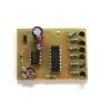
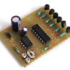
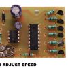
The “CD4017, 555 Timer 6 Channel LED Chaser with Adjustable Speed” is an electronic circuit commonly used in hobbyist and DIY electronics projects. Let’s break down the components and functionality of this circuit:
CD4017 Decade Counter/Divider (CD4017 IC): The CD4017 is a CMOS integrated circuit that acts as a decade counter or divider. It has ten output pins (labeled Q0 to Q9) that toggle sequentially in response to clock pulses. In this LED chaser circuit, the CD4017 is used to control the sequencing of LEDs, causing them to light up in a chasing pattern.
555 Timer IC: The 555 timer is another integrated circuit known for its versatility in generating various types of timing signals, such as oscillations, pulses, and delays. In this circuit, the 555 timer is configured as an astable multivibrator to produce clock pulses. The frequency of these pulses can be adjusted to control the speed of the LED chasing effect.
6 Channel LED Chaser: The circuit is designed to control six LEDs (Light Emitting Diodes) that light up in a sequence or pattern. The CD4017 IC is used to drive the LEDs one at a time in a loop, creating the chasing effect.
Adjustable Speed: The speed of the LED chasing effect is adjustable, primarily by changing the resistor and capacitor values in the 555 timer circuit. Adjusting these components alters the frequency of the clock pulses, which, in turn, changes how quickly the LEDs cycle through their sequence.
Operation: When the circuit is powered on, the 555 timer generates clock pulses that are fed into the CD4017 IC. The CD4017 sequentially activates its output pins (Q0 to Q9) one by one in response to each clock pulse. Each of these output pins is connected to an LED, causing them to light up in sequence. The adjustable speed control influences the time delay between each LED activation, controlling the chasing speed.


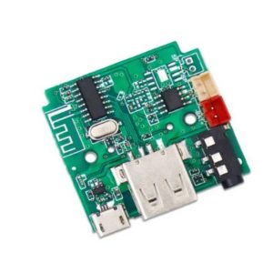 Bluetooth FM USB Aux Card and Remote
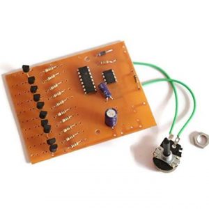 Electronic Components, Industrial Electronic Parts, Led Chaser Board
 DC Power Supply and Adapter
 Industrial Electronic Parts, Limit Switch
There are no reviews yet.